Reparatieverslag - Netgear GS724T V3 (English)
30-May-2019

Recover Netgear GS724T from bricked state
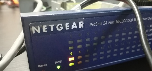
Trying to upgrade the Netgear GS724T(V3) switch from version 4.1.0.9 to version 5.4.2.27 the image went corrupted and so the switch was not able to boot after a reboot command. The power LED stayed orange and was not able to become green again.
After an extended search on the internet, there was no available solution and the switch should be send back to Netgear for a replacement. I haven't bought the switch myself so the guarantee was not valid anymore. So.. I had to find another solution to solve this.
Searching the internet for a possible solution, the biggest problem was that this switch doesn't have a UART (serial) interface. Connecting one of the network ports to another switch doesn’t light up the interface ports also. It looks like the switch is bricked without the possibility to restore it again.
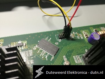
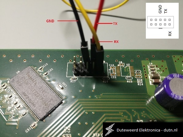
After probing with an oscilloscope, I was able to locate the (according to Netgear, the not existing) UART interface. This interface is located on the mainboard, described as J1.

To connect the UART pins to a computer, I have used a USB to Serial interface (TTL/Serial converter; also known as FTDI Tool). Connect the TX pin on de mainboard to the RX pin of the converter, de RX on the mainboard to the TX pin of the converter and de GND to GND.

Open a terminal window (like putty) on the computer and connect this to the associated COM port (9600 8n1) and power-up the Netgear switch. The following text should appear on the screen:
		CFE-NTSW-5.0.3 for GS7XXT (32bit,SP,BE,MIPS)
		Build Date: Thu Jul  2 19:58:21 IST 2009 (ndbabu@xl-hyda-42)
		Copyright (C) 2000,2001,2002,2003,2004,2005 Broadcom Corporation.

		Initializing Arena.
		Initializing Devices.
		Board : GS724T
		CPU type 0x29050: 200MHz
		Total memory: 0x4000000 bytes (64MB)

		Total memory used by CFE:  0x83EA2000 - 0x83FFFA40 (1432128)
		Initialized Data:          0x83EEADF4 - 0x83EEBF10 (4380)
		BSS Area:                  0x83EEBF10 - 0x83EFDA40 (72496)
		Local Heap:                0x83EFDA40 - 0x83FFDA40 (1048576)
		Stack Area:                0x83FFDA40 - 0x83FFFA40 (8192)
		Text (code) segment:       0x83EA2000 - 0x83EEA52B (296235)
		Boot area (physical):      0x03E61000 - 0x03EA1000
		Relocation Factor:         I:E42A2000 - D:E42A2000
		Compression Supported:     7zip
		nvram_commit: will write 168 bytes from 83f00f48
		result 168 (360)

		Checking Factory Default.
		Factory Default button is NOT asserted.
		Loader:elf Filesys:raw Dev:flash0.os File: Options:(null)
		Loading:
		Validating the code file..
		Flash image is 4232969 bytes,  CRC 0000A0DF
		Flash image size is bogus!
		Failed.
		Could not load flash0.os:: File not found
		DHCP registration failed on device eth0
		-----------------
		eth0: 9 sent, 27 received, 0 interrupts
			9 tx interrupts, 27 rx interrupts
		Loader:elf Filesys:raw Dev:flash0.os1 File: Options:(null)
		Loading:
		Validating the code file..
		Flash image is 4232969 bytes,  CRC 0000A0DF
		Flash image size is bogus!
		Failed.
		Could not load flash0.os1:: File not found
After experimenting with the CFE interface, I was able to load a new image from a TFTP server by using the following commands & actions:
Note: 192.168.0.2 is the TFTP server in this case, you should see the following output on the terminal console:
		CFE> ifconfig -addr=192.168.0.10 -gw=192.168.0.1 -mask=255.255.255.0 eth0
		Device eth0:  hwaddr 00-00-xx-xx-xx-xx, ipaddr 192.168.0.10, mask 255.255.255.0
				gateway 192.168.0.1, nameserver not set
		*** command status = 0

		CFE> flash -noheader 192.168.0.2:netgear41.stk flash0.os
		Reading 192.168.0.2:netgear41.stk: Done. 3533668 bytes read
		Programming...done. 3533668 bytes written
		nvram_commit: will write 168 bytes from 83f2038c
		result 168 (360)
		*** command status = 0
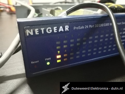
After a reboot command, the switch should boot normaly and the Power LED should turn green again. Please update the switch to the latest firmware available.

If you have any questions about this topic, please contact me
If this was interesting for you, please consider a donation via PayPal here